CfCbazar
DIY Tools
Home Smart Deals DIY Games Music WorkToken Terms Cookies Help
DIY Circuit Op‑amp controlled NPN current source

OPAMP BJT Current Regulator

A stable ≈1 A linear current regulator using an op‑amp and a single NPN transistor. The op‑amp forces a constant voltage across a 10 Ω sense resistor, producing a precise and low‑noise constant current.

15 V supply ≈0.96 A regulated output Single‑transistor linear design
Simulation Result
Measured output current
Graph
OPAMP BJT current regulator simulation

How the Regulator Works

Op‑amp feedback sets the current.

Concept

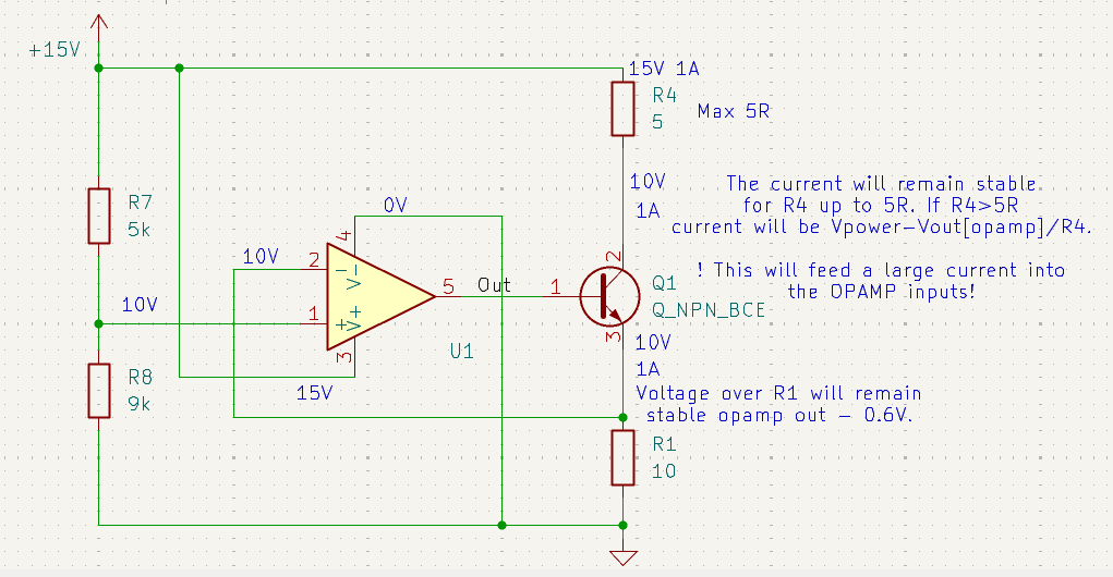
The op‑amp compares a fixed reference voltage to the voltage across the 10 Ω sense resistor. It drives the base of the NPN transistor so that the sense resistor always sees the reference voltage. This forces a constant current:

I = Vref / Rsense
Vref ≈ 9.64 V (from 5 kΩ / 9 kΩ divider)
Rsense = 10 Ω → I ≈ 0.964 A

Because the op‑amp continuously adjusts the transistor drive, the current remains stable even if the load or supply voltage changes.

Transistor Stage

One NPN transistor with 5 Ω collector resistor.

Hardware

The collector of the NPN transistor is fed from the 15 V supply through a 5 Ω resistor. Since the transistor is the only path to the sense resistor, the current through the 5 Ω resistor is the same as the regulated output current:

I ≈ 0.964 A → VR4 ≈ 0.964 A × 5 Ω ≈ 4.82 V

This places the collector at about 10.18 V while the emitter sits at 9.64 V, leaving VCE ≈ 0.54 V. The transistor operates close to saturation but still under op‑amp control.

If R4 is increased above 5 Ω, the regulator will no longer reach 0.96 A and the op‑amp will saturate.

Thermal Considerations

Linear regulation = heat.

Thermals

With ≈0.96 A flowing:

10 Ω sense resistor: ≈9.3 W
5 Ω collector resistor: ≈4.6 W
Transistor: ≈0.5 W

The resistors dissipate most of the heat and must be high‑power types. The transistor requires modest heatsinking.

Tuning the Output Current

One formula defines everything.

Design

The output current is set by: I = Vref / Rsense.

Ways to adjust:

  • Change the divider ratio (R7 / R8) to modify Vref.
  • Change the sense resistor value.

Examples:

  • Rsense = 5 Ω → I ≈ 1.93 A
  • Rsense = 20 Ω → I ≈ 0.48 A